Choosing the right self priming pump begins with understanding the actual job, not just comparing catalog prices. A pump that works well in a clean-water test may struggle with wastewater, air pockets, sludge, or changing suction conditions. The site matters. Measure the suction lift, discharge distance, flow rate, fluid temperature, and expected solids before selecting equipment.
Experienced operators often inspect the pump location before reading the specification sheet. A long suction pipe, sharp elbows, or a partially closed valve can reduce performance quickly. Check the manufacturer’s performance curve, recommended pipe size, maximum particle passage, seal materials, and maintenance requirements. Confirm that the pump can remove trapped air without repeated manual priming. It should also match the motor, power supply, and operating schedule.
No pump fits every site.
A practical choice balances capacity, durability, energy use, and service access. Cast iron may suit many water applications, while stainless steel or specialized coatings can better resist certain fluids. These decisions require professional guidance when the liquid is abrasive, corrosive, hot, or chemically unstable. Independent test data and recognized safety standards can improve confidence, but they do not replace field verification.
It is easy to overvalue maximum flow. Real performance may fall under difficult suction conditions. Allow room for uncertainty. Speak with qualified suppliers, compare several documented models, and inspect the installation after commissioning. A careful selection process may take longer, yet it can prevent frequent clogging, seal damage, and expensive downtime.
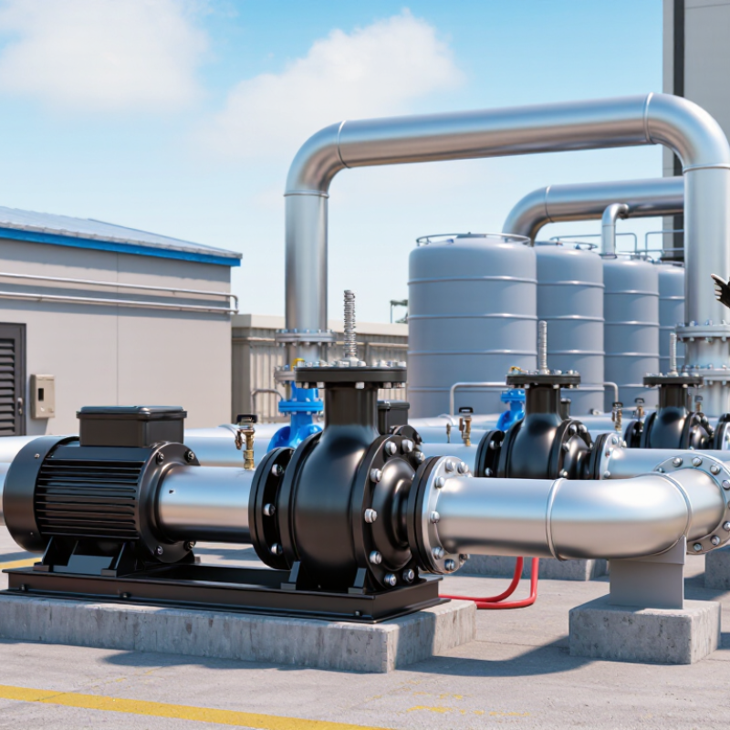
A self-priming pump can remove air from its suction line without manual filling after installation. Its casing retains enough liquid for the next startup. When the impeller rotates, it mixes trapped air with liquid. This lighter mixture moves toward the discharge chamber. Atmospheric pressure then pushes liquid upward through the suction pipe. Once the air leaves, the pump returns to ordinary centrifugal operation. The process is practical, but not magic. Excessive suction lift, leaking joints, or a dry casing can prevent priming.
The U.S. Department of Energy’s Improving Pumping System Performance report states that pumping systems may consume 25% or more of electricity in some industrial facilities. The IEA also reports that motor-driven systems use about 43–46% of global electricity. These figures make correct pump selection important. Check flow rate, total dynamic head, liquid temperature, viscosity, and solids content. A pump sized only by pipe diameter may waste energy and suffer unstable operation. The boundary between “self-priming” and “always ready” is often misunderstood.
Tips: Keep the suction pipe short and airtight. Install a foot valve when the application requires liquid retention. Confirm the manufacturer’s maximum priming lift under real conditions. Test startup after a long shutdown. A small air leak can look like a pump failure. Do not ignore noise, vibration, or slow priming; each may reveal poor sizing or an unsuitable layout. For reliable decisions, compare field measurements with the DOE report and Hydraulic Institute guidance.
Start with the required flow rate, measured in gallons or litres per minute. Estimate the real demand, not the maximum number shown on a process sheet. A storage tank may need 80 L/min during transfer, while a drain line may need far less. Add the vertical lift from the liquid surface to the discharge point. Then include pipe friction, bends, valves, and filters. This total is the pump’s required head. In field checks, I measure the pipe route carefully because a few extra elbows can change performance. My early estimates were often too optimistic.
Tips: Record flow and head separately. Check the pump curve at your operating point. Avoid selecting only by outlet size. Leave a sensible margin, but do not oversize the pump excessively.
Fluid conditions can change the selection quickly. Water-like liquids are simple, but thick fluids need more power and may reduce flow. Check temperature, acidity, suspended solids, and entrained air. A liquid containing sand can wear internal parts, while a hot fluid may affect seals and priming reliability. Confirm the maximum suction lift under actual conditions. Long suction lines deserve extra attention. A pump may prime well in a test tank but struggle through a narrow, dirty hose. Review viscosity data and solids size with a qualified engineer. Real installations are rarely perfect.
How to Choose the Right Self Priming Pump?
Match pump materials and design to the application, not merely the catalog flow rate. A self-priming pump must remove air from the suction line before stable liquid transfer begins. Measure suction lift, pipe length, fluid temperature, viscosity, and solids content on site. A five-meter suction lift can behave differently with warm oil than with clean water. Small details matter.
Material selection should follow chemistry and operating temperature. Cast iron may suit clean, non-aggressive water, while stainless steel or engineered polymers can better resist chloride-rich wash water. Check elastomer compatibility separately; the casing may survive while seals swell or crack. The NACE IMPACT study estimated global corrosion costs at 3.4% of worldwide gross domestic product, showing why material decisions deserve financial attention. That shortcut fails.
Design also affects lifetime cost. Choose an impeller passage large enough for the expected solids, and verify the check valve’s sealing reliability. Oversized passages can reduce blockage risk, but they may sacrifice efficiency. The U.S. Department of Energy’s Improving Pumping System Performance sourcebook reports that pumping systems can represent nearly 20% of industrial electricity use. Efficiency is not a minor specification. Compare duty-point efficiency, priming time, maintenance access, and replacement-part availability. I have seen designs selected from ideal laboratory conditions, then exposed to rag-like debris and frequent starts. The pump worked, but not gracefully. Recheck field data before approval.
| Application or Fluid | Typical Fluid Characteristics | Recommended Self-Priming Design | Preferred Wetted Materials | Seal and Elastomer Considerations | Typical Operating Temperature | Important Selection Criteria |
|---|---|---|---|---|---|---|
| Clean water transfer | Low viscosity, low solids content, generally non-corrosive | Self-priming centrifugal pump with a standard impeller and a large priming chamber | Cast iron for general service; stainless steel for improved corrosion resistance | Mechanical seal with ceramic or silicon-carbide faces; EPDM is commonly suitable for water | Typically 0–80°C, depending on seal, elastomer, and pump construction | Check suction lift, priming time, available net positive suction head, flow rate, and discharge head |
| Wastewater and sewage | Contains suspended solids, fibrous material, and occasional debris | Non-clog, vortex, or recessed-impeller self-priming centrifugal design | Cast iron or ductile iron casing; stainless steel or hardened alloy wear components when abrasion is present | Oil-lubricated mechanical seals are often selected; EPDM suits many water-based waste streams | Typically 0–40°C for municipal wastewater service | Specify maximum solids diameter, fiber tolerance, cleanout access, abrasion resistance, and clog resistance |
| Abrasive slurry | High concentration of sand, mineral particles, ash, or other abrasive solids | Recessed-impeller, vortex, or heavy-duty centrifugal pump with generous internal clearances | High-chrome alloy, hardened iron, abrasion-resistant steel, or replaceable rubber lining | Silicon-carbide mechanical seals or packed glands may be used; elastomer selection depends on the liquid chemistry | Typically 0–60°C, subject to lining and seal limits | Evaluate solids concentration, particle size, specific gravity, wear rate, pump speed, and maintenance access |
| Corrosive chemicals | Acids, alkalis, oxidizers, or other chemically aggressive liquids | Self-priming diaphragm pump or chemically resistant centrifugal pump; diaphragm designs tolerate intermittent dry running better | Polypropylene, PVDF, PTFE-lined components, or stainless steel selected according to chemical compatibility | PTFE diaphragms and seals are widely used for chemical resistance; FKM or EPDM may be suitable for specific chemicals | Commonly −20–90°C, depending on material combination and chemical concentration | Confirm a complete chemical compatibility chart, vapor pressure, required flow stability, leakage control, and dry-run requirements |
| Oily water and hydrocarbons | Low to medium viscosity, potentially flammable, with oil, fuel, or grease content | Self-priming centrifugal or diaphragm pump designed for hydrocarbon service | Ductile iron, carbon steel, aluminum, or stainless steel; material choice depends on fluid chemistry and site regulations | NBR is common for many petroleum-based fluids; FKM may be selected for higher temperature or chemical resistance | Typically 0–80°C, subject to fluid volatility and seal limits | Consider hazardous-area certification, grounding, static control, vapor pressure, seal compatibility, and fire-safe installation |
| Food, beverage, and sanitary liquids | Low to medium viscosity; hygienic handling and cleanability are required | Sanitary self-priming centrifugal or liquid-ring pump with smooth internal passages | 316L stainless steel with polished wetted surfaces and sanitary clamp connections | Food-grade EPDM, PTFE, or FKM seals; select materials compatible with cleaning and sanitizing chemicals | Typically 0–95°C, depending on the cleaning cycle and elastomer rating | Check hygienic certification, surface finish, drainability, clean-in-place capability, dead-leg control, and shear sensitivity |
| Viscous liquids | Higher viscosity than water, such as oils, syrups, coatings, or concentrated detergents | Self-priming positive-displacement diaphragm, progressive-cavity, or gear-type design where appropriate | Stainless steel, carbon steel, or chemically resistant plastics selected for the liquid | PTFE, FKM, NBR, or EPDM must be matched to both the fluid and operating temperature | Often 0–80°C, but viscosity and seal temperature limits must be verified | Account for viscosity-related flow reduction, starting torque, pressure relief, suction-line diameter, and allowable shear |
| Dewatering and construction water | Water containing sand, silt, small stones, or intermittent air entrainment | Heavy-duty self-priming centrifugal pump with a wear-resistant impeller and accessible cleanout cover | Cast iron or ductile iron; hardened components or replaceable wear plates for abrasive service | Mechanical seal faces should be selected for abrasive water; silicon carbide offers high wear resistance | Typically 0–40°C | Prioritize rapid priming, portability, solids handling, wear-part availability, fuel or motor requirements, and suction hose integrity |
| Hot water and condensate | Elevated temperature, possible flashing, and reduced available suction pressure | Temperature-rated centrifugal or liquid-ring self-priming design; avoid standard pumps when vapor pressure is high | Stainless steel or temperature-rated cast iron, depending on water chemistry | High-temperature mechanical seals and suitable graphite, PTFE, or temperature-rated elastomers are required | Often 80–120°C for specially rated equipment; verify the exact pump and seal limits | Calculate NPSH available at operating temperature, control suction losses, and prevent cavitation or vapor lock |
Choosing the right self-priming pump begins with actual priming conditions, not catalog flow alone. A pump should remove air from suction piping and establish liquid flow without repeated manual filling. Measure vertical lift, pipe length, fittings, and liquid temperature before comparing models. A small leak at one threaded joint can defeat a strong priming system. Keep suction piping short, airtight, and gently rising where possible. Test it cold and again at operating temperature.
Priming performance matters during startup, while efficiency affects every running hour. Compare rated flow at the required head, not at the lowest resistance point. Oversizing can increase power use and cause unstable operation. Check motor input, hydraulic efficiency, and expected duty cycle together. Record priming time, discharge pressure, and power consumption during a practical test. For dirty or viscous liquids, published efficiency may fall sharply. That detail is easy to miss.
Maintenance needs often determine the real operating cost. Inspect the casing, seals, impeller, and check valve at scheduled intervals. A pump that primes quickly may still require frequent seal replacement. Provide access for draining, cleaning, and removing blockages. Do not assume self-priming means safe dry running. One common mistake is ignoring air leaks after installation. Recheck flange bolts, gaskets, and flexible connections after the first week. Field conditions rarely match perfect test conditions.
Comparison of typical priming performance, hydraulic efficiency, and annual maintenance requirements under similar operating conditions.
Lower priming time and fewer maintenance hours generally indicate easier operation, while higher hydraulic efficiency can reduce energy consumption. Actual results vary with suction lift, fluid viscosity, solids content, pipe design, duty cycle, and installation conditions.
Choosing the right self-priming pump starts with the actual duty, not the pipe label. Record flow rate, total dynamic head, fluid temperature, solids size, and suction lift. A pump rated for 30 cubic meters per hour may deliver far less at high lift. Measure the route, including elbows and valves. I once trusted an old drawing and underestimated suction losses. The installation struggled until the pipe length was checked on site. That mistake was avoidable. Measure twice.
Select a motor with useful margin, but avoid excessive oversizing. Oversizing can increase energy use, noise, and seal wear. Check the pump curve at the intended operating point. Confirm whether the casing, impeller, and seals suit abrasive, corrosive, or warm liquids. A strainer may protect the impeller, but a fine screen can restrict priming. Choose features such as dry-run protection, drain access, a transparent priming chamber, or variable-speed control when they solve a real problem. Not every option helps.
Installation configuration determines whether self-priming performance remains reliable. Keep the suction pipe short, straight, and airtight. Use a gradual elbow near the inlet, and support heavy pipe independently. Position the pump close to the liquid source, with enough clearance for inspection. Check foot valves, automatic priming arrangements, and discharge routing against the manufacturer’s instructions. In practice, poor alignment causes many pump failures. Recheck levels and connections after the first operating cycle. Keep it accessible. Field conditions rarely match the plan exactly.