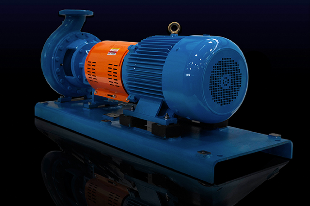
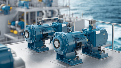
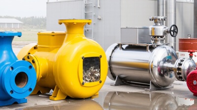
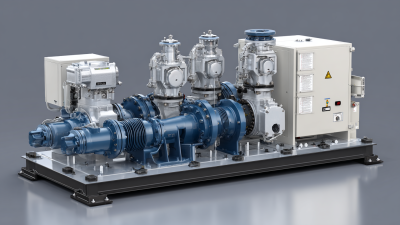
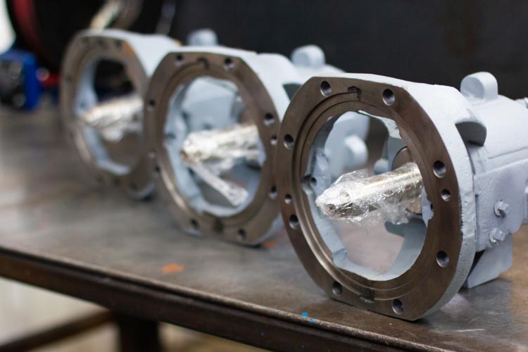
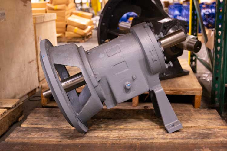
| End-Suction Centrifugal Pump |
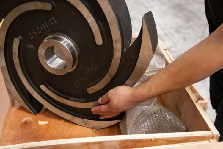
A rotating impeller adds velocity to the liquid, and the casing converts part of that velocity into pressure. |
Single pump, baseplate-mounted, direct-coupled to a motor; optional standby pump for critical service. |
Flow: approximately 5–1,500 m³/h
Head: approximately 10–150 m
Fluid: low- to medium-viscosity liquids
|
Water transfer
Cooling water
General process service
Irrigation
|
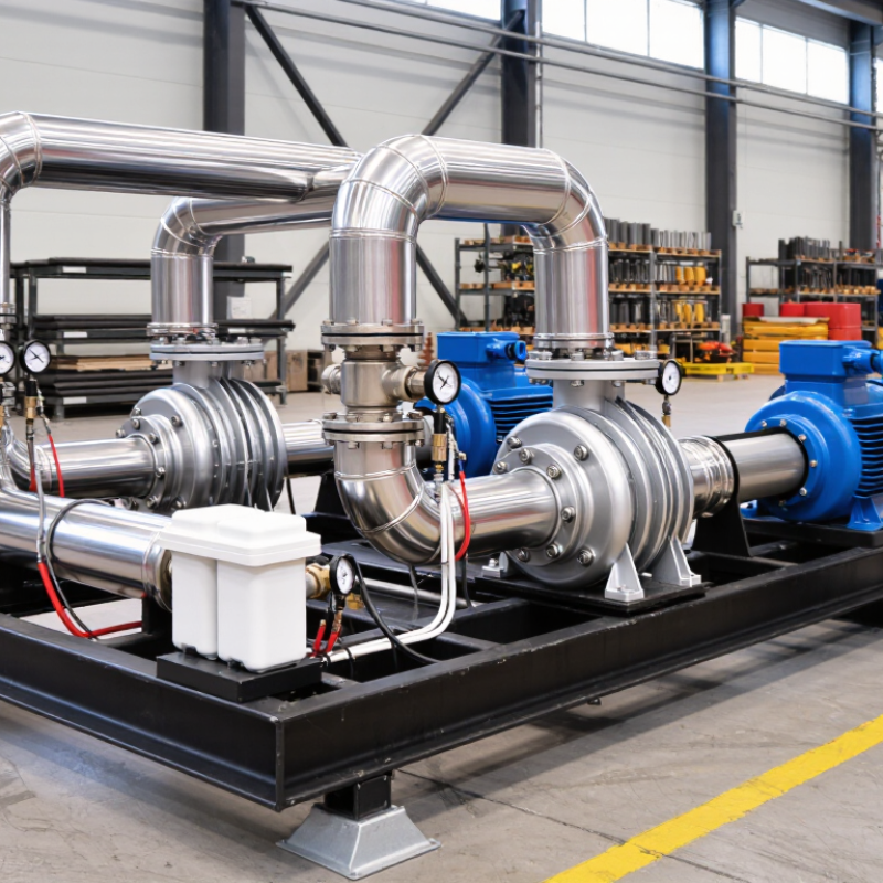
Isolation valves, check valve, suction strainer where appropriate, pressure gauges, flexible coupling, coupling guard, drain connections, and a structural baseplate. |
Simple layout, broad availability, efficient operation near the design point, and relatively easy maintenance. |
Requires adequate net positive suction head available (NPSHA); performance decreases at low flow, and the pump should not normally operate far from its best efficiency point. |
| Horizontal Split-Case Centrifugal Pump |
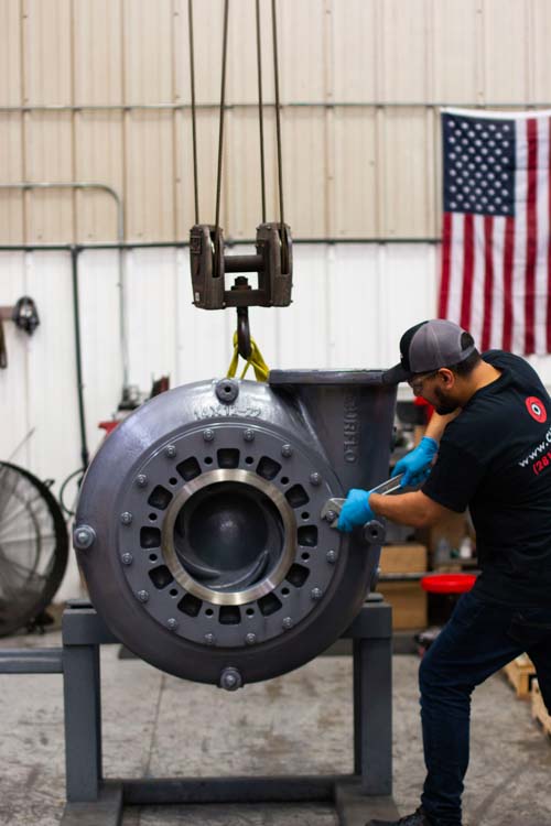
The impeller rotates within a horizontally split casing. The casing can usually be opened without disconnecting the main pipework. |
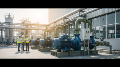
Horizontal pump on a rigid fabricated base, commonly arranged as duty/standby or multiple duty pumps with common headers. |
Flow: approximately 50–10,000 m³/h
Head: approximately 20–250 m
Fluid: clean or lightly contaminated liquids
|
Municipal water
Firewater systems
Large cooling circuits
Industrial utilities
|
Suction and discharge manifolds, isolation and check valves, pressure and vacuum gauges, coupling guard, baseplate, lifting points, and optional vibration monitoring. |
High flow capacity, good hydraulic efficiency, robust construction, and convenient access to rotating parts. |
Requires adequate foundation stiffness and alignment; the layout must allow casing access and sufficient clearance for maintenance. |
| Vertical Turbine Pump |
A vertical shaft drives one or more impellers submerged in the liquid. The pump lifts liquid from a tank, wet well, or deep intake. |
Vertical pump assembly mounted on a fabricated discharge head or deck-mounted base; the motor is positioned above the liquid source. |
Flow: approximately 20–15,000 m³/h
Head: approximately 20–500 m
Suction condition: flooded or submerged intake
|
Raw-water intake
Cooling-water intake
Deep wells
Wet wells
|
Discharge head, column pipe, line shaft, bowl assembly, motor, discharge elbow or spool, non-return valve, and access platform where required. |
Uses a submerged intake, can handle large flow rates, and reduces the need for a long suction line. |
Requires sufficient structural support and shaft alignment; access for inspection and lifting must be considered during layout. |
| Multistage Centrifugal Pump |
Several impellers arranged in series progressively increase the pressure of the liquid at each stage. |
Horizontal or vertical pump mounted on a common baseplate; often configured with duty/standby pumps and a common discharge manifold. |
Flow: approximately 1–500 m³/h
Head: approximately 100–1,000 m
Fluid: clean, low-viscosity liquids
|
Boiler feed
Reverse osmosis feed
High-pressure water service
Pressure boosting
|
Interstage or discharge pressure instrumentation, minimum-flow bypass, isolation valves, check valve, coupling guard, baseplate, and pressure relief protection where needed. |
Generates high discharge pressure with a comparatively compact footprint and can provide stable pressure boosting. |
Minimum-flow protection is often essential; liquid cleanliness, seal selection, axial thrust, and operating pressure must be evaluated. |
| Progressive Cavity Pump |
A helical rotor turns inside an elastomeric stator, forming sealed cavities that move fluid at a controlled rate. |
Horizontal skid with motor and gearbox, hopper or feed inlet, discharge piping, pressure protection, and optional variable-speed drive. |
Flow: approximately 0.1–500 m³/h
Differential pressure: commonly up to approximately 60 bar, depending on design
Fluid: viscous or solids-bearing liquids
|
Sludge
Dosing
Polymers
Viscous process fluids
|
Hopper, feed screw where required, pressure gauge, relief valve or torque protection, variable-speed drive, flush connections, and flexible connectors. |
Low-pulsation flow, good solids-handling capability, and accurate flow control over a broad speed range. |
Dry running can rapidly damage the stator; abrasive solids, temperature, elastomer compatibility, and suction conditions require careful review. |
| Rotary Gear Pump |
Meshing gears transport liquid from the suction side to the discharge side. The trapped volume between the gear teeth and casing creates positive displacement. |
Compact baseplate skid with motor and gearbox, suction strainer, pressure relief valve, bypass line, and flow instrumentation. |
Flow: approximately 0.01–100 m³/h
Differential pressure: commonly up to approximately 25 bar
Fluid: clean, lubricating, viscous liquids
|
Fuel transfer
Lubricating oil
Resins
Chemical transfer
|
Relief valve, suction strainer, pressure gauge, check valve where required, flexible coupling, coupling guard, gearbox, and optional heating jacket. |
Provides predictable displacement per revolution, compact installation, and good performance with viscous liquids. |
Discharge pressure must be protected against deadheading; abrasive particles can accelerate wear, and viscosity affects power demand and slip. |
| Air-Operated Double-Diaphragm Pump |
Compressed air alternately moves two diaphragms, creating suction and discharge strokes through check valves. |
Portable or fixed skid with pump, air filter-regulator, control valve, pulsation dampener, isolation valves, and containment tray. |
Flow: approximately 0.01–60 m³/h
Discharge pressure: commonly up to approximately 8 bar
Fluid: corrosive, shear-sensitive, or solids-bearing liquids
|
Chemical transfer
Slurry handling
Wastewater
Batch transfer
|
Compressed-air preparation unit, air control valve, pulsation dampener, pressure gauge, check valves, flexible hoses, spill containment, and grounding provisions where applicable. |
Self-priming, capable of running dry for limited periods, suitable for many difficult fluids, and available without an electric motor at the pump. |
Air consumption and noise can be significant; pulsation, diaphragm compatibility, freezing of compressed air, and exhaust ventilation should be addressed. |
| Peristaltic Hose Pump |
Rotating rollers or shoes compress a flexible hose, moving discrete volumes of liquid through the hose without direct contact with the pump mechanism. |
Low-speed geared drive on a baseplate, commonly with variable-speed control, suction and discharge hoses, pressure protection, and hose monitoring. |
Flow: approximately 0.001–100 m³/h
Differential pressure: commonly up to approximately 15 bar
Fluid: abrasive, viscous, or shear-sensitive liquids
|
Abrasive slurries
Mining chemicals
Dosing
Wastewater sludge
|
Flexible hose, roller or shoe assembly, gearbox, variable-speed drive, pressure relief device, hose rupture detector, and spill containment. |
Only the hose contacts the pumped fluid, excellent solids handling, low shear, and strong suction capability. |
Hose life depends on pressure, speed, temperature, and chemical compatibility; excessive discharge pressure can cause hose failure. |
| Metering Diaphragm Pump |
A reciprocating diaphragm displaces a measured volume on each stroke. Stroke length and frequency control the dosing rate. |
Chemical dosing skid with one or more pumps, calibration column, injection assembly, back-pressure valve, relief valve, pulsation dampener, and control panel. |
Flow: approximately 0.001–10 m³/h
Discharge pressure: commonly up to approximately 400 bar, depending on design
Fluid: chemicals and low- to medium-viscosity liquids
|
Water treatment
pH adjustment
Disinfection
Process additives
|
Chemical tank, suction lance, calibration column, pressure and relief devices, injection quill, pulsation dampener, leak detection, and control instrumentation. |
High dosing accuracy, broad turndown capability, and isolation of the pumped fluid from the drive mechanism in diaphragm designs. |
Requires correct materials compatibility, proper priming and venting, pulsation control, and protection from blocked discharge lines. |