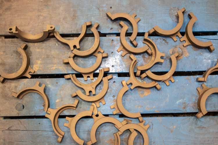
Choosing the right pump parts in 2026 will require more than matching a model number.
Industrial pumping systems face higher energy costs, stricter efficiency targets, and aging equipment. The U.S. Department of Energy reports that pumping systems can consume significant industrial electricity, often reaching 20% to 25% of total facility usage. That makes every impeller, seal, bearing, and coupling relevant to operating cost.
The global pumps market also continues to expand. Grand View Research estimates that the market could grow steadily through 2030, driven by water infrastructure, manufacturing, energy, and chemical processing. However, market growth does not make every replacement part suitable. A stainless-steel impeller may resist corrosion, but it can still fail under abrasive slurry. A mechanical seal may fit the shaft, yet leak when temperature or pressure changes.
Dr. Lev Nelik, a recognized pump systems consultant and author, has emphasized this practical principle: “A pump is only as good as the system around it.” That idea should guide every pump parts decision. Compatibility includes material, dimensions, pressure rating, temperature, speed, fluid chemistry, and installation conditions.
Small details matter.
A two-millimeter clearance error can create vibration, heat, and premature wear. Supplier documentation, service records, and field measurements provide stronger evidence than price alone. Still, no selection process is perfect. Catalog data may be incomplete, and operating conditions can change after installation. That is why this guide examines specifications, failure patterns, lifecycle cost, and supplier reliability before recommending pump parts for 2026.
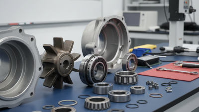
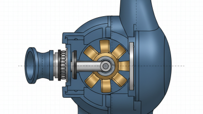
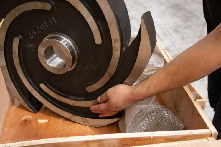
Pump parts do more than keep equipment running. Each component controls flow, pressure, sealing, or shaft movement. Impellers transfer energy to the fluid. Casings guide that fluid through the pump. Mechanical seals prevent leakage around the rotating shaft. Bearings support rotation and reduce vibration. Wear rings manage internal clearance and protect efficiency. Gaskets create static seals between connected surfaces. In field maintenance, I have found that small clearances can change performance significantly.
Common part types include impellers, shafts, seals, bearings, sleeves, wear rings, gaskets, and casing sections.
Selection depends on the pump’s design and operating conditions. Check fluid chemistry, temperature, pressure, flow rate, and rotation speed.
Then compare shaft diameter, mounting dimensions, seal arrangement, and material strength. Stainless alloys may suit corrosive fluids, while hardened materials can resist abrasive particles. Compatibility is not only about fitting the bolt holes. It also involves tolerances, thermal expansion, and surface finish.
Tips: Record the old part’s measurements before ordering. Photograph its orientation and wear pattern. Read the pump drawing, service manual, and inspection records. Ask a qualified technician to verify critical dimensions. Do not trust appearance alone. A similar impeller may have a different vane angle. I once overlooked a minor seal dimension, and the replacement failed early. Check twice. Allow for human error. Test the repaired pump under controlled conditions, watching vibration, temperature, pressure, and leakage.
Start by identifying the exact pump model before ordering any replacement part. Read the nameplate carefully. Record the model code, serial number, flow rate, head, speed, and operating temperature. Photograph the plate and the worn component. This simple record prevents costly guesswork.
Then confirm the pump design. Is it centrifugal, positive displacement, vertical, horizontal, single-stage, or multistage? Each design uses different sealing methods, clearances, and shaft arrangements. Do not trust appearance alone.
Check the required components against the service conditions. Common parts include:
Match each part with the pumped liquid, pressure, temperature, and rotational speed. Material compatibility matters. A seal that works with clean water may fail quickly in abrasive or corrosive fluid. Measure shaft diameter, bore size, keyway dimensions, and installation length. Small errors can create vibration.
I have seen technicians replace a seal correctly but overlook a worn sleeve. The new seal failed within days. That mistake was avoidable.
Compare the assembly drawing, maintenance records, and removed parts together. Catalog data can be incomplete. Even experienced teams should recheck tolerances and rotation direction. When model information is missing, consult a qualified pump engineer and provide clear measurements. Guessing feels faster, but it often becomes the most expensive step.
Choosing pump parts begins with operating conditions, not a familiar material. Start with the liquid. Record temperature, pressure, viscosity, pH, dissolved gases, and suspended solids during normal and upset conditions. A clean process sample can hide abrasive particles during startup or flushing. Therefore, inspect strainers, drained sediment, and maintenance photographs before ordering an impeller, wear ring, or seal.
Material selection should follow actual chemical exposure. Stainless alloys may suit many fluids, while chlorides, acids, or high temperatures may require a more resistant grade. Elastomers need separate attention because swelling can cause leakage, even when metal parts remain sound. Match the shaft, casing, impeller, and fasteners as one system. One weak component can shorten service life. Check hardness, corrosion allowance, pressure rating, and temperature limits against traceable technical data. Request material certificates for critical duties.
Hydraulic specifications matter just as much. Confirm flow, head, speed, efficiency, suction conditions, and solids passage using measured data, not only an old nameplate. A part with the correct diameter may still change balance or reduce clearance. During installation, measure shaft runout, coupling alignment, gasket compression, and seal faces. Small details matter. A tidy calculation can still mislead when the pump cycles frequently or runs below its design point. Review early vibration, leakage, and energy readings, then revise the spare-parts specification if field evidence disagrees. That step is easy to skip, and sometimes necessary.
When selecting pump parts, begin with quality, not the lowest quoted price. Check alloy specifications, machining tolerance, surface finish, and heat-treatment records. A worn shaft sleeve may look acceptable but fail quickly under abrasive water. Ask for dimensional inspection reports and material traceability before ordering.
Small details matter.
Cost should include installation time, downtime, freight, and expected service life. A cheaper impeller can become expensive after repeated balancing or early replacement. I once underestimated delivery risk because the supplier promised stock without confirming the exact model. That mistake delayed maintenance for several days.
Availability must be verified in writing.
Request real inventory status, production lead time, and emergency shipping options.
Supplier support also deserves careful testing.
Can the technical team interpret drawings, confirm measurements, and suggest compatible materials? Do they provide clear installation guidance and respond within a reasonable time? Good support includes replacement advice, inspection records, packing protection, and help after delivery. Ask difficult questions early.
Silence is information. A supplier may offer impressive documents but weak practical assistance. Leave room for doubt, and check references from similar pumping conditions before committing.
How to Choose the Right Pump Parts in 2026?
Choosing pump parts starts with verification, not appearance. Check the pump model, serial number, shaft diameter, impeller dimensions, seal size, and connection type. A part can look identical yet fail because its clearance differs by a few millimeters. Confirm operating pressure, temperature, flow rate, and fluid compatibility. These details determine whether the part will perform safely and last.
Installation requirements deserve equal attention. Review the service manual before removing anything, and photograph the original assembly. Clean contact surfaces, use the correct gasket, and align the shaft carefully. During field work, I have seen small alignment errors create vibration within minutes. I once trusted a familiar measurement and skipped a second check. That mistake caused unnecessary rework. Experience helps, but careful verification matters more.
Tips
Keep a written parts record. Include dimensions, materials, replacement dates, and operating conditions. Choose materials that tolerate the pumped fluid and temperature, not merely the cheapest option. Inspect seals, bearings, wear rings, and fasteners during scheduled maintenance. Look for scoring, cracks, discoloration, and unusual noise. Replace related worn parts when necessary, but avoid changing healthy components without evidence. A simple inspection light and calibrated measuring tools can prevent expensive downtime. If the installation instructions are unclear, pause and consult a qualified technician before restarting the pump.
| Pump Part | Fit Verification | Key Specifications to Match | Installation Requirements | Maintenance Needs | Typical Replacement Trigger | Selection Priority |
|---|---|---|---|---|---|---|
| Mechanical Seal | Confirm shaft diameter, stationary-seat dimensions, rotating-face arrangement, seal chamber depth, and spring direction. Check the pump model and original seal drawing. | Material compatibility, pressure rating, temperature range, shaft speed, face combination, and elastomer type. | Clean the shaft and seal chamber; inspect for burrs; lubricate only as permitted by the seal instructions; avoid touching polished seal faces. | Inspect for leakage, heat discoloration, vibration, and abnormal noise. Check alignment and dry-running events that can damage the faces. | Visible leakage, face damage, hardened elastomers, excessive wear, or repeated leakage after correct installation. | High |
| Gasket or O-Ring | Match groove dimensions, cross-section, inside diameter, flange profile, and compression requirements. Never select by outside diameter alone. | Fluid compatibility, temperature rating, pressure rating, hardness, and resistance to swelling or chemical attack. | Use the correct groove and seating surface; remove old material; avoid twisting O-rings; apply compatible lubricant where specified. | Check for flattening, cuts, extrusion, cracking, swelling, and compression-set during scheduled inspections. | Leakage, permanent deformation, cracking, chemical swelling, or removal of the connected joint. | High |
| Impeller | Verify pump series, impeller diameter, vane count, bore, keyway, balance grade, rotation direction, and required clearance. | Flow rate, total head, rotational speed, fluid solids content, material, and closed-, open-, or semi-open design. | Check shaft and key condition; set wear clearance according to the pump service manual; confirm correct rotation before full operation. | Inspect for erosion, corrosion, clogging, cracks, imbalance, and vane wear. Clean passages without damaging the surfaces. | Reduced flow or head, excessive vibration, damaged vanes, severe wear, or performance outside the duty point. | High |
| Wear Ring | Measure both the impeller and casing wear surfaces. Match inside diameter, outside diameter, axial width, and specified running clearance. | Material, clearance limits, interference fit, operating temperature, and fluid abrasiveness. | Remove the old ring without damaging the casing; verify fit and concentricity; restore the specified clearance after assembly. | Measure clearance at planned intervals and inspect for scoring, ovality, and abrasive wear. | Clearance exceeds the service limit, efficiency drops, internal recirculation increases, or surfaces become scored. | High |
| Shaft or Shaft Sleeve | Confirm overall length, diameter, keyway, threads, seal location, bearing seats, runout limit, and coupling dimensions. | Material strength, corrosion resistance, hardness at seal contact areas, maximum speed, and allowable runout. | Protect machined surfaces; check straightness and runout with suitable measuring equipment; verify key fit and coupling alignment. | Inspect for grooving, corrosion, fretting, bending, and wear beneath seals or bearings. | Excessive runout, deep seal grooves, damaged threads or keyways, corrosion loss, or inability to maintain alignment. | High |
| Bearings | Match bearing designation, bore, outside diameter, width, internal clearance, load rating, and mounting arrangement. | Radial and axial loads, speed, operating temperature, lubrication method, and environmental contamination. | Use clean tools and correct mounting force; apply force only to the ring being fitted; do not strike the bearing directly. | Monitor temperature, vibration, noise, lubrication condition, and shaft movement. Prevent water and dirt ingress. | Rising temperature, abnormal noise, vibration, rough rotation, discoloration, or excessive radial or axial play. | High |
| Coupling Element | Verify coupling size, bore, keyway, spacer length, torque capacity, speed rating, and compatibility with the coupling hubs. | Transmitted torque, misalignment limits, service factor, temperature, electrical isolation needs, and guard clearance. | Align shafts before installation; set the correct gap; install the guard; tighten fasteners to the specified torque. | Inspect for cracks, hardening, tooth wear, loose fasteners, and signs of angular or parallel misalignment. | Cracking, deformation, excessive backlash, repeated element failure, or misalignment that cannot be corrected. | Medium |
| Bearing Housing | Match mounting pattern, bearing seats, shaft centerline height, oil or grease arrangement, and seal locations. | Material, bearing fit tolerances, lubrication capacity, drain and vent provisions, and operating temperature. | Clean all mating surfaces; inspect bearing bores for fretting; verify centerline and fastener condition before final tightening. | Check oil level or grease condition, housing temperature, contamination, cracks, and mounting-bolt tightness. | Damaged bearing seats, cracks, persistent lubricant leakage, distortion, or inability to maintain bearing alignment. | Medium |
| Suction or Discharge Flange Gasket | Match flange nominal size, pressure class, bolt-hole pattern, gasket type, thickness, and facing arrangement. | Fluid compatibility, pressure and temperature rating, flange material, bolt load, and surface finish. | Clean flange faces; center the gasket; avoid using a gasket that blocks the flow path; tighten bolts in a cross pattern. | Inspect for external leakage, bolt relaxation, flange distortion, and gasket extrusion during system checks. | Leakage, damaged flange faces, disassembly of the joint, or evidence of chemical or thermal degradation. | High |
| Check Valve | Confirm line size, connection type, flow direction, pressure class, cracking pressure, and installation orientation. | Flow rate, fluid viscosity, solids content, pressure, temperature, and allowable pressure loss. | Install the arrow in the flow direction; provide adequate pipe support; keep the valve accessible for inspection and cleaning. | Check for reverse flow, water hammer, sticking, noise, seat wear, and debris accumulation. | Reverse flow, failure to close, excessive pressure loss, repeated water hammer, or damaged seat and disc. | Medium |
| Pressure Gauge or Sensor | Match connection size, thread standard, pressure range, accuracy, wetted materials, electrical output, and environmental rating. | Normal and maximum pressure, pulsation, temperature, fluid compatibility, calibration range, and signal type. | Install with an isolation valve or suitable snubber where needed; protect from vibration and excessive temperature; verify sealing method. | Compare readings with a reference instrument, inspect for leakage, and check calibration at the interval required by the control system. | Inconsistent readings, zero drift, damaged display, blocked impulse path, leakage, or failed calibration. | Medium |
| Motor or Drive-End Fan | Verify motor frame, power, voltage, frequency, speed, mounting arrangement, shaft dimensions, and overload protection. | Required pump speed, torque, duty cycle, enclosure, efficiency class, ambient temperature, and hazardous-area requirements where applicable. | Confirm electrical isolation, grounding, rotation direction, coupling alignment, ventilation, and correct overload settings. | Keep ventilation passages clean; inspect terminals, bearings, vibration, temperature, and fan condition. | Overheating, insulation failure, abnormal current, excessive vibration, damaged fan, or inability to reach operating speed. | High |
| Baseplate and Mounting Fasteners | Match bolt pattern, pump and motor footprint, shaft centerline height, anchor locations, and allowable structural load. | Material, stiffness, anchor size, grout or isolation arrangement, vibration level, and corrosion environment. | Level and secure the base; correct soft foot; align the pump and driver after final piping connection; tighten anchors correctly. | Inspect anchor torque, corrosion, grout condition, cracks, vibration, and changes in alignment. | Persistent misalignment, cracked grout, loose anchors, deformation, corrosion loss, or abnormal vibration. | Medium |
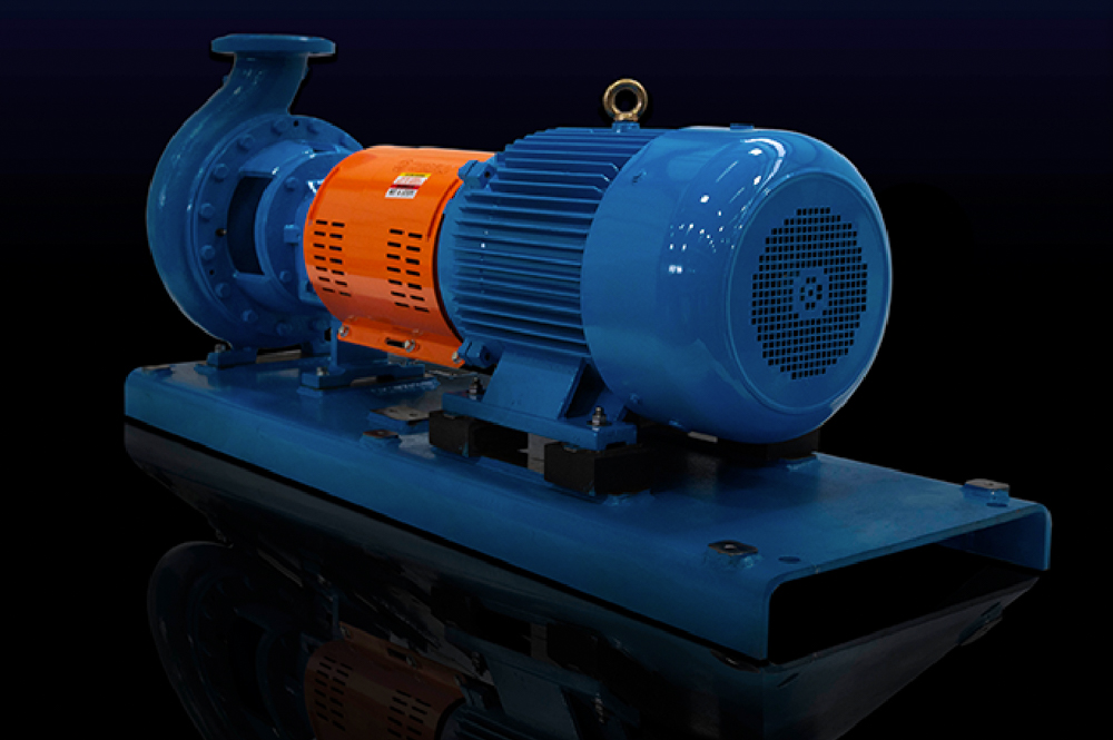
Selection rule: Always confirm the pump model, serial information, dimensional drawing, operating duty point, fluid properties, and applicable service manual before ordering or installing any replacement part. Use the manufacturer’s specified tolerances, torque values, clearances, and safety procedures for final verification.