Cost of Repairing vs. Replacing ANSI Pumps: A Comprehensive Analysis

Blog

What Are Centrifugal Pumps and How Do They Work?

Centrifugal pumps are among the most widely used machines for moving water, chemicals, fuel, and process fluids. Their operation may look simple, but reliable performance depends on several connected details. An electric motor or engine rotates an impeller inside a casing. Fluid enters near the impeller’s center, gains velocity, and moves toward the outer edge. The casing then helps convert part of that velocity into pressure. The principle is simple. The application is not always simple.

This guide explains how centrifugal pumps create flow, how their main components interact, and why operating conditions matter. It examines impellers, casings, shafts, mechanical seals, bearings, suction lines, and discharge systems. Practical issues receive attention, including priming, air leaks, cavitation, blocked strainers, and operation far from the pump’s best efficiency point. Small details matter. A partially closed valve or undersized suction pipe can cause vibration, heat, noise, and premature wear. Manufacturer performance curves provide essential guidance, but real installations may behave differently from laboratory conditions. That difference deserves careful thought. Pipe friction, fluid temperature, viscosity, elevation, and changing demand can alter results significantly. The discussion follows established hydraulic principles and common maintenance practices. It also encourages users to verify specifications against manufacturer manuals, site measurements, and applicable safety requirements. Understanding these limits helps engineers, operators, and maintenance teams select, install, and monitor centrifugal pumps with greater confidence.
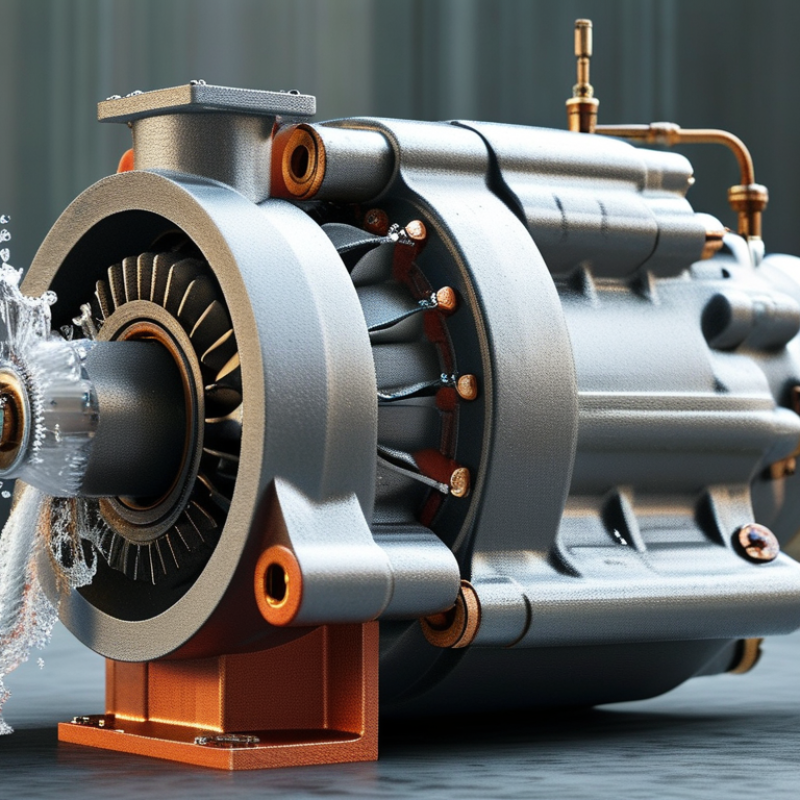
What Are Centrifugal Pumps and How Do They Work?

What Is a Centrifugal Pump?

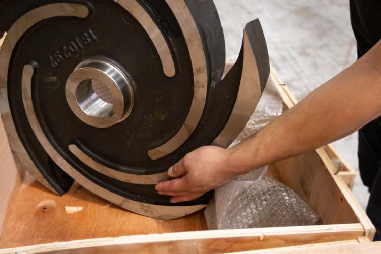
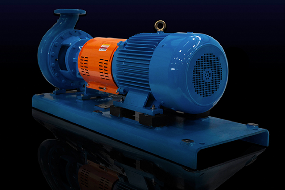
A centrifugal pump is a machine that moves liquid by converting rotational energy into fluid movement. An electric motor or engine turns an impeller inside a fitted casing. The impeller has curved blades that guide the liquid outward. This action creates higher pressure near the discharge outlet.

Liquid usually enters through the impeller’s center, called the eye. Rotation accelerates it toward the casing wall. The casing then slows the liquid and converts part of its velocity into pressure. The pressurized liquid leaves through the discharge pipe. It sounds simple. However, the pump cannot reliably move air-filled lines without proper priming.

In field inspections, technicians check unusual vibration, seal leakage, blocked strainers, and unstable pressure. These symptoms may indicate cavitation, a condition caused by insufficient suction pressure. Cavitation can produce a harsh crackling sound and damage the impeller. Correct pipe sizing, adequate liquid level, and suitable operating speed help prevent it. The textbook explanation often ignores installation details. In practice, a well-designed pump can still perform poorly when valves, elbows, or air pockets restrict the suction line.

What Are Centrifugal Pumps and How Do They Work? - What Is a Centrifugal Pump?

Data Dimension Typical Data or Definition How It Relates to Pump Operation
Basic Definition A dynamic pump that converts mechanical energy into fluid pressure and velocity. It continuously moves liquid by adding energy to the liquid rather than trapping and displacing a fixed volume.
Primary Energy-Transfer Component Impeller with curved vanes, driven by a rotating shaft. The impeller accelerates the liquid outward from its eye toward its outer diameter.
Flow Path Liquid usually enters axially at the impeller eye and leaves radially or diagonally. The change in flow direction and velocity allows pressure to be developed inside the pump casing.
Pressure-Conversion Component Volute casing or diffuser passages. These passages reduce liquid velocity and convert part of the velocity energy into static pressure.
Operating Sequence Prime the pump, start rotation, draw liquid into the impeller eye, accelerate the liquid, then discharge it through the casing. Most centrifugal pumps must contain liquid before startup because they generally cannot pump air effectively.
Flow Rate Common installations range from less than 1 m³/h to several thousand m³/h, depending on pump size and design. Actual flow depends on impeller diameter, rotational speed, system resistance, and the selected operating point.
Developed Head Many general-purpose pumps provide approximately 5–250 m of head; specialized multistage designs can provide considerably more. Head represents the energy added per unit weight of liquid and is not the same as pressure for every fluid.
Typical Efficiency Approximately 40–90%, with larger, properly selected pumps generally achieving higher efficiency. Efficiency varies with pump size, liquid properties, speed, impeller design, and distance from the best-efficiency point.
Best-Efficiency Point The flow rate at which hydraulic efficiency is normally highest and hydraulic loads are better balanced. Continuous operation close to this point usually reduces vibration, recirculation, seal wear, and energy consumption.
Affinity Relationships For the same pump: flow is approximately proportional to speed; head is proportional to speed²; power is proportional to speed³. These relationships help estimate the effect of speed changes, although real systems also depend on piping resistance and pump efficiency.
Cavitation Risk Cavitation can occur when the liquid pressure at the impeller inlet falls below the liquid vapor pressure. It may cause noise, vibration, unstable flow, and damage to impeller surfaces. Available NPSH should exceed required NPSH with a suitable margin.
Liquid Compatibility Suitable for many low- to medium-viscosity liquids, including water, process fluids, and some chemicals. Very viscous liquids, liquids containing large solids, or liquids that release gas may require a different pump design.
Main Advantages Simple construction, steady flow, compact layout, and suitability for continuous operation. The rotating design generally has fewer reciprocating parts, which can simplify maintenance and reduce pulsation.
Main Limitations Usually requires priming, has limited suction lift, and may lose performance with highly viscous or gas-filled liquids. Correct installation, adequate inlet pressure, proper alignment, and operation near the selected duty point are important.
Common Applications Water supply, irrigation, cooling systems, heating systems, wastewater handling, fire-water systems, and industrial process circulation. The pump is selected by matching required flow, total dynamic head, liquid properties, temperature, and operating conditions.
Core Selection Data Required flow, total dynamic head, liquid temperature, viscosity, density, vapor pressure, solids content, motor speed, and available NPSH. Accurate selection prevents undersupply, excessive energy use, cavitation, premature wear, and operation far from the best-efficiency point.

Key Components and Their Functions

What Are Centrifugal Pumps and How Do They Work?

Key Components and Their Functions

Centrifugal pumps transfer liquid by converting rotational energy into fluid velocity and pressure. The motor turns the shaft, while the shaft drives the impeller. Curved impeller vanes push liquid outward from the eye. The casing then collects that flow and guides it toward the discharge nozzle. This conversion is simple, but alignment matters greatly.

The suction nozzle brings liquid into the pump. The impeller creates the main hydraulic action. Bearings support the rotating shaft and control vibration. A mechanical seal limits leakage where the shaft enters the casing. Wear rings maintain the internal clearance around the impeller. Excessive clearance reduces efficiency, even when the pump still appears operational. A pressure gauge can reveal this hidden decline.

Installation details often decide performance. A clogged suction strainer starves the impeller. Poor pipe support can load the casing and shaft. Insufficient net positive suction head may cause cavitation, producing a sharp gravel-like sound. I have seen operators blame the pump before checking air leaks near the suction flange. That assumption wastes time.

The U.S. Department of Energy’s Pumping System Assessment Tool guidance indicates that pumping systems may consume 25–50% of a facility’s industrial electricity. European Commission ecodesign studies estimate pumps use about 22% of motor electricity in relevant applications. These figures are not universal. Actual consumption depends on flow, head, control method, and operating hours. A partially closed valve can hide an oversized pump, while variable-speed control may reduce unnecessary throttling losses.

What Are Centrifugal Pumps and How Do They Work?

Typical centrifugal pump performance: discharge head decreases as flow rate increases.

A centrifugal pump uses a rotating impeller to increase the liquid's velocity. The volute or diffuser then converts much of that velocity into pressure. The chart shows a realistic typical relationship between flow rate and discharge head: as more liquid flows through the pump, the available head generally decreases. Key components include the impeller, casing, shaft, mechanical seal, bearings, and suction and discharge connections.

How a Centrifugal Pump Moves Fluid

What Are Centrifugal Pumps and How Do They Work?

A centrifugal pump moves fluid by turning mechanical energy into flow and pressure. Inside the casing, a rotating impeller pulls liquid through its central opening, called the eye. The liquid then travels outward along the impeller blades. It gains speed as the impeller spins.

The casing slows this fast-moving liquid. This converts part of its velocity into pressure. The pressurized fluid then leaves through the discharge outlet and enters the connected pipework. Meanwhile, lower pressure near the impeller eye draws in more liquid. This creates a continuous movement, provided the pump remains filled and the suction path stays open.

The process is simple, but real systems are less forgiving. Air entering the suction line can interrupt flow. Poor pipe design may create turbulence or cavitation, producing a harsh rattling sound. A pump can look normal while losing efficiency. That detail deserves attention.

Tips: Check the suction line for leaks and confirm the pump is properly primed. Watch for unusual vibration, heat, or noise. Keep the fluid within the pump’s rated temperature and pressure range. Field experience also shows that small installation errors can cause large performance losses. Measurements are safer than assumptions.

Factors That Affect Pump Performance

What Are Centrifugal Pumps and How Do They Work?

A centrifugal pump uses a rotating impeller to move liquid through a system. The impeller adds velocity, and the casing converts much of that velocity into pressure. Performance depends on more than motor power. Liquid properties, pipe design, and operating conditions all influence the result.

Flow rate and head must match the system’s real demand. Excessive pipe friction can reduce flow, especially in long lines or narrow hoses. Every valve, elbow, filter, and entrance adds resistance. Small changes matter. Liquid viscosity also affects efficiency. Thick fluids usually require more power and may produce less flow than expected. Temperature can change viscosity and vapor pressure, creating additional risk.

Cavitation is another serious factor. It occurs when pressure near the impeller falls too low, causing vapor bubbles to form and collapse. The pump may sound like it contains gravel. Installers should check available suction pressure, fluid temperature, and suction pipe conditions. Air leaks can create similar symptoms, which makes diagnosis imperfect. That uncertainty deserves attention.

A pump should operate near its intended performance range. Running far from the best efficiency point can increase vibration, heat, and seal wear. Maintenance records should include flow, pressure, vibration, and motor current. These measurements reveal gradual changes before failure becomes obvious. Yet readings taken only once can mislead. Conditions vary, and a clean-looking system may still have hidden restrictions. Proper sizing, careful installation, and repeated field checks provide more dependable results.

Common Types and Applications of Centrifugal Pumps

Centrifugal pumps use a rotating impeller to move liquid. The impeller adds velocity, while the casing converts much of that velocity into pressure. It sounds simple. Real systems are less forgiving. Flow changes when pipe friction, liquid temperature, or suction conditions shift.

Common designs suit different duties. End-suction pumps handle general water transfer, HVAC circulation, and irrigation. Split-case pumps support higher flows in municipal and industrial systems. Multistage pumps use several impellers for high-pressure boiler feed, reverse-osmosis pretreatment, and tall-building supply. Vertical turbine pumps work well in deep wells or tanks. Self-priming models help where air may enter the suction line.

Selection must follow the operating curve, not only the nameplate flow. The U.S. Department of Energy reports that pumping systems can represent about 25% of industrial motor energy use, making efficiency a practical cost issue (DOE, Improving Pumping System Performance, 2006). A pump running far from its best efficiency point may vibrate, overheat, and waste power. The Hydraulic Institute and Europump identify energy as a major portion of pump life-cycle cost in their Pump Life Cycle Costs guide. Small details matter. A clogged strainer can imitate pump failure. Dry running can damage seals within minutes. In field practice, engineers should check suction pressure, alignment, valve position, and actual flow before replacing equipment. The first diagnosis is not always right.

Proud Member Of Curry Supply Holdings
Since 1932

Tour Our State-of-the-Art Facility

Click for a Quick Quote