Cost of Repairing vs. Replacing ANSI Pumps: A Comprehensive Analysis

Blog

2026 Top Centrifugal Pump Parts and Their Functions

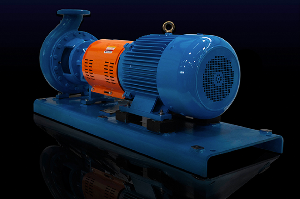
Centrifugal pumps move liquid by turning rotational energy into flow and pressure. Their performance depends on several components working together, not just a powerful motor. Understanding centrifugal pump parts helps operators select equipment, recognize wear, and discuss repairs more clearly.

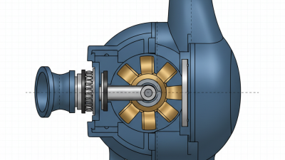
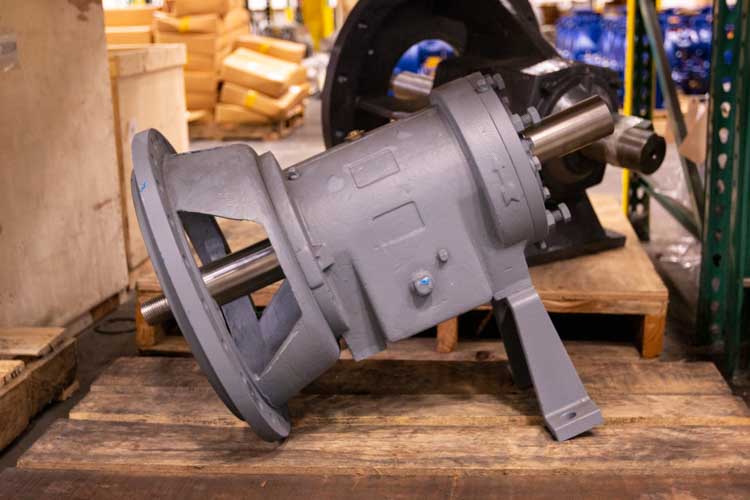
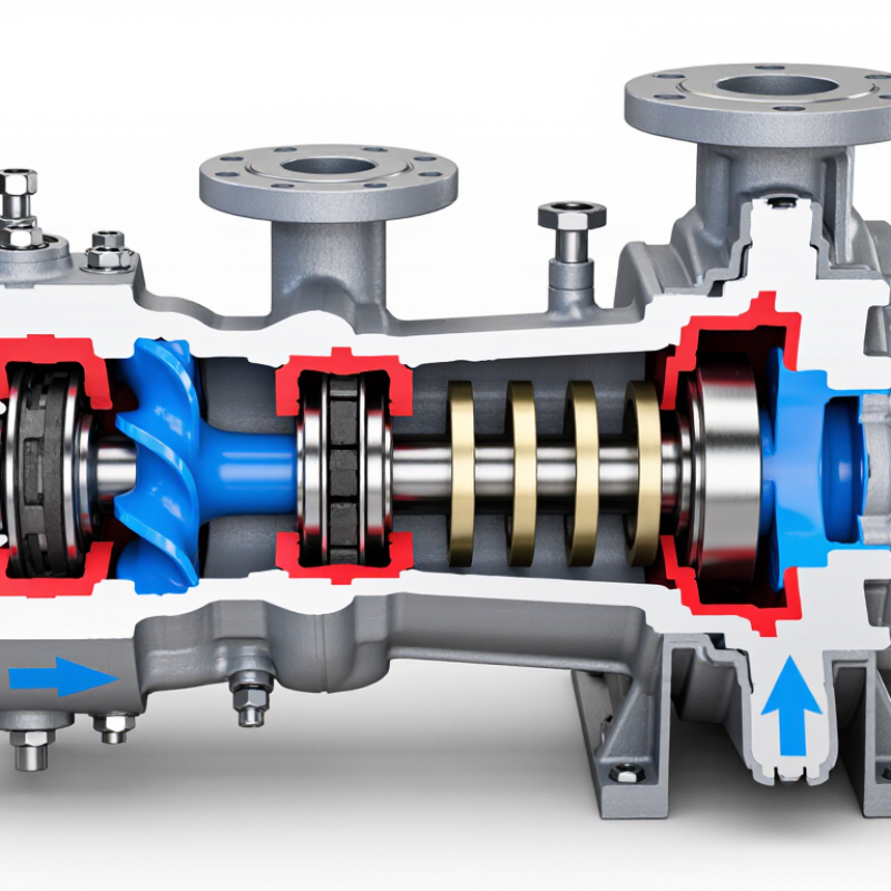
The impeller accelerates liquid outward, while the casing collects and directs it toward the discharge. The shaft transfers torque to the impeller, and bearings keep the rotating assembly aligned. A mechanical seal or packing limits leakage around the shaft. Wear rings, where fitted, reduce internal recirculation and help maintain efficiency. Each part has a distinct job. Small details matter.

In practice, symptoms rarely point to one component with certainty. Vibration may relate to bearing wear, misalignment, cavitation, or operating conditions. Leakage can indicate seal damage, but installation and fluid properties matter too. A part may look intact and still perform poorly; inspection alone is not always enough. That is worth remembering.

This guide introduces the main centrifugal pump parts and explains what each one does, how the components interact, and which signs may suggest attention is needed. It also highlights why pump design, liquid temperature, pressure, and maintenance history affect part selection. Use the pump manufacturer’s documentation for model-specific limits and service procedures. No general overview replaces those details. Just a starting point.
2026 Top Centrifugal Pump Parts and Their Functions

Pump Casing: Containing Fluid and Converting Velocity into Pressure

A centrifugal pump casing does more than hold water in place. It forms the pressure boundary around the impeller and directs liquid toward the discharge. In a volute casing, the flow passage gradually widens, slowing the liquid and recovering some of its velocity as static pressure. The impeller supplies energy; the casing helps convert it. Not magic. Its geometry matters.

The U.S. Department of Energy’s Improving Pumping System Performance: A Sourcebook for Industry reports that pumping systems can account for 25–50% of energy use in some industrial operations. That figure covers whole systems, not casings alone, but it shows why avoidable hydraulic losses deserve attention. A rough internal surface, worn cutwater, or poorly matched discharge passage can disturb flow and reduce performance. Inspect for erosion, corrosion, cracks, and cavitation pitting, especially near the impeller and tongue. Small damage can matter. Casing material, pressure rating, and operating temperature must suit the actual liquid and duty. A casing inspection cannot diagnose every efficiency problem, though; impeller wear, pipework, and operating conditions also need checking.
2026 Top Centrifugal Pump Parts and Their Functions

Pump Casing: Containing Fluid and Converting Velocity into Pressure

The chart shows ideal static pressure rise for water as velocity decreases from an inlet velocity of 8 m/s. It is calculated using Bernoulli’s principle at the same elevation, with water density assumed to be 1,000 kg/m³. Real pump casings experience flow losses, so actual pressure recovery is lower.

Impeller: Adding Energy to the Flowing Fluid

2026 Top Centrifugal Pump Parts and Their Functions

Impeller: Adding Energy to the Flowing Fluid

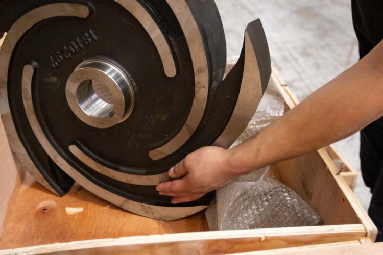
Inside a centrifugal pump, the impeller turns with the shaft and transfers mechanical energy to the liquid. Its curved vanes guide fluid from the inlet toward the outer edge. As the impeller spins, the liquid accelerates outward, gaining velocity. The pump casing then helps convert that velocity into pressure. The impeller does not create pressure alone. Clearances, rotational speed, and casing geometry also shape performance. Even a small wear groove can disturb flow and reduce efficiency. During inspection, check for erosion, cracks, and uneven deposits. Uneven deposits matter.

The U.S. Department of Energy’s Improving Pumping System Performance sourcebook reports that pumping systems account for nearly 20% of global electricity demand. That figure covers pumping systems broadly, not impellers alone, but it shows why their performance matters. The correct impeller depends on the fluid, required flow, and operating conditions. A design suited to clean water may perform poorly with a viscous or solids-laden liquid. Field conditions rarely match a tidy diagram. That mismatch deserves attention. Operators should compare actual flow and pressure with the pump’s intended operating range, then inspect the impeller if readings drift. A worn impeller may be the cause, but it is not the only possible one.

Shaft, Coupling, and Motor: Transferring Rotational Power

In a centrifugal pump, the motor supplies rotation, but the shaft and coupling make that rotation useful at the impeller. The motor shaft turns at a set speed; the coupling connects it to the pump shaft while transmitting torque. Depending on the pump design, the coupling may accommodate slight thermal growth or minor alignment variation. It is not a cure for poor installation. Small gaps matter.

The pump shaft carries torque to the impeller and must resist bending from hydraulic and mechanical loads. Bearings support the shaft, while a seal around it limits leakage where it exits the casing. During maintenance, technicians check coupling alignment with suitable instruments, secure the fasteners, and confirm that guards are fitted. Excessive vibration, heat, or unusual noise can indicate misalignment, imbalance, or worn parts; compare readings with the pump’s operating history. No single symptom proves the cause. Measurements can miss changes as piping warms, so a final check under stable operating conditions is valuable.

Bearings and Mechanical Seals: Supporting Motion and Preventing Leakage

Bearings and mechanical seals do quiet, essential work inside a centrifugal pump. Bearings support the rotating shaft and help keep the impeller aligned with the casing. When lubrication is clean and suitable, the shaft can turn with less friction. Heat leaves clues. A rising bearing temperature, unusual vibration, or a change in operating noise may signal wear or misalignment.

The mechanical seal limits leakage where the shaft exits the pump casing. Its two precision faces run close together, with a thin fluid film helping reduce friction and wear. Dry running, abrasive particles, or sudden pressure changes can damage those faces. Even a small leak deserves attention; it may be tempting to dismiss a few drops, but that can hide a worsening problem. Seal life also depends on correct installation and operating conditions, not just the part itself.

Tips: Check bearing temperature and vibration trends during routine inspections, rather than relying on a single reading. Look for fresh residue around the seal and listen for changes after startup. Follow the pump’s service instructions for lubrication and clearances. Do not guess. A careful inspection may still miss an underlying cause, so record what changed and compare it with earlier readings.

Wear Rings and Pump Connections: Managing Clearances and Directing Flow

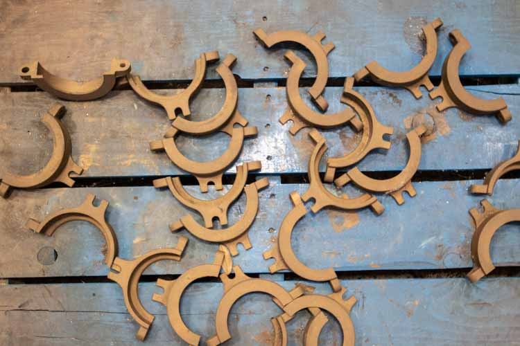
Wear rings control the gap between a centrifugal pump’s rotating impeller and stationary casing. They limit internal recirculation, helping the pump maintain flow and pressure. The clearance must be large enough to avoid rubbing as parts warm and shift, but not so large that water slips back easily. It is a narrow balance. Abrasive particles, corrosion, or prolonged operation can enlarge the gap and reduce performance.

Pump connections also shape how reliably fluid reaches and leaves the impeller. A suction pipe that is too small, poorly aligned, or crowded with sharp bends can create uneven flow and vibration. On the discharge side, fittings and valves add resistance. Check that gaskets do not protrude into the pipe, where they may disturb the flow. Even a neat installation can have hidden alignment problems, so inspection matters.

Tips: Measure wear-ring clearance against the pump’s service specifications, not a guessed rule. Look for scoring, uneven wear, and leaks. Support piping independently, and avoid forcing a flange into alignment with the pump. A simple check can prevent a costly surprise.

2026 Top Centrifugal Pump Parts and Their Functions - Wear Rings and Pump Connections: Managing Clearances and Directing Flow

Part or Connection Location and Flow Role Clearance or Fit Consideration What to Inspect Service Significance
Casing wear ring Fits in the casing around the impeller eye; forms a replaceable running surface near the impeller inlet. The running clearance is set between the ring bore and the impeller hub or mating ring. Use the pump’s service specification; the required fit depends on size, materials, temperature, and service. Measure bore diameter, roundness, scoring, and evidence of rubbing. Check that the ring is securely seated. Controls internal leakage from the high-pressure discharge region toward the impeller eye. Excessive clearance can reduce hydraulic efficiency and capacity.
Impeller wear ring Mounted on the impeller at the mating surface with the casing ring; rotates with the impeller. The diametral running clearance is the difference between the mating diameters. Confirm the specified cold clearance and account for operating temperature and material expansion. Check wear depth, concentricity, attachment, and contact marks. Replace or restore only within approved repair limits. Provides a renewable wear surface instead of allowing the impeller or casing to wear directly. Correct clearance helps limit recirculation.
Back wear ring Used on some designs at the rear of the impeller, where it mates with a casing or back-cover ring. Set clearance to the design specification; verify axial position and ensure the ring does not rub during operation. Inspect mating faces for uneven wear, deposits, scoring, and signs of excessive axial movement. May reduce leakage behind the impeller and can contribute to managing axial hydraulic forces, depending on pump design.
Suction nozzle and connection Connects the suction piping to the pump inlet and directs liquid toward the impeller eye. Match the connection size and pressure class to the piping and pump. Avoid a sudden reduction immediately at the suction nozzle. Check gasket condition, flange alignment, leaks, strain, and whether the piping arrangement traps air or creates flow disturbance. A well-arranged suction path supports even inlet flow and helps reduce the risk of cavitation and unstable performance.
Discharge nozzle and connection Carries pressurized liquid from the pump casing into the discharge piping. Select piping, gasket, and bolting for the specified pressure, temperature, and fluid. Support the pipe so its weight is not carried by the nozzle. Inspect flange faces, gasket seating, bolt condition, leakage, and alignment with connected piping. Directs pump output into the system. Excessive external piping loads can distort the casing and affect alignment or internal clearances.
Flanged connection Bolted joint commonly used to connect pump nozzles to process piping or removable spool pieces. Flange dimensions and pressure rating must match. Tighten bolts in a controlled cross-pattern using the applicable procedure. Look for damaged sealing faces, incorrect gasket placement, uneven bolt loading, and signs of leakage. Provides a serviceable pressure-containing joint; correct alignment and gasket compression support reliable sealing.
Threaded or auxiliary connection May serve vents, drains, seal-flush lines, cooling lines, or instrument connections, depending on the pump arrangement. Use the specified thread form, compatible sealing method, and suitable materials. Do not overtighten fittings into the casing. Confirm ports are correctly identified, open when required, free of blockage, and leak-free after service. Supports safe venting, draining, sealing, cooling, or monitoring; incorrect connections can impair pump operation.
Clearance measurement and acceptance Applies to wear-ring interfaces and other close-running internal fits during inspection or overhaul. Measure mating diameters with suitable calibrated instruments. Compare the calculated clearance with the pump-specific maintenance limits rather than a universal value. Record as-found and as-left dimensions, measurement locations, instrument identification, and any corrective work. Consistent measurement helps identify wear trends and confirms that the assembled pump has adequate running clearance without excessive internal leakage.

Note: Wear-ring clearances, connection ratings, and repair limits are design- and service-specific. Always use the applicable pump drawings and maintenance instructions for final acceptance.

Proud Member Of Curry Supply Holdings
Since 1932

Tour Our State-of-the-Art Facility

Click for a Quick Quote